
An oil leak from the cam bridge (cambridge) cover is one of the most common gremlins on the Audi/VW EA888 2.0T. Resealing it the right way means keeping the camshafts locked in place while the cover is off — and that's exactly what the AHMCNC EA888 camshaft retaining tools are built for. This guide walks through the full reseal procedure, from prepping the engine to torquing the cover back down.
The process below is based on a transverse layout as found in a 2020 Volkswagen GTI with a Gen3 EA888, but the reseal is very similar on longitudinal setups such as Audi Quattro vehicles. Because of manufacturing changes across the EA888's production run and the different chassis it's installed in (FWD vs. AWD), there may be slight variations in how certain components (coolant pipes, etc.) come off. The installation of our tools, however, is identical regardless of engine configuration.

If you already know the cam bridge / valve cover reseal procedure, skip ahead to Section 2 for the overview and installation of the camshaft retaining tools.
The guide is broken into three sections:
- Section 1 — Preparation and removal of engine components
- Section 2 — Overview and installation of the camshaft retaining tools
- Section 3 — Cam bridge / cylinder head cover removal and reseal procedure
Removing Engine Components
This section covers the engine components you'll need to remove to prepare for installing the camshaft retaining tools. The lists below aren't every hand tool you'll touch — they're the general set you can expect to use, plus the consumables to have on hand before you start. Some OE Audi/VW special tools make certain steps easier but aren't strictly required.
Tool List
- AHMCNC EA888 cam bridge reseal tool
- Hose clamp removal tool — large channel-lock pliers, or OE VAS6362*
- Ignition coil removal tool — Gen1/Gen2 coils use OE T40039*; Gen3 coils use OE T10530*
- Coolant hose clamp pliers — OE 3094*
- Ratchets & sockets (regular and Torx)
- Wrenches, pliers, gasket scraper(s), assorted picks
- Small bungee cord(s)
* = Optional OE Audi/VW tool
Parts List
- Vacuum pump gasket
- High-pressure fuel pump O-ring
- Anaerobic flange sealant
- PCV gasket or valve (depending on condition)
- Upper timing cover gasket(s)
- Replacement cylinder head cover bolts
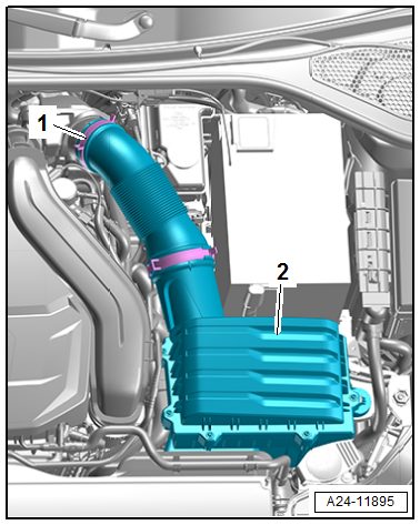
Step 1. Remove Air Filter Housing & Charge Air Pipes
- 1.1 — Disconnect the vacuum hose -1-.
- 1.2 — On vehicles equipped with secondary air, remove connecting pipe -2-.
- 1.3 — For all other vehicles: loosen the hose clamp -1- and remove the air duct hose.
- 1.4 — Pull the air filter housing -2- upward off the ball pins.
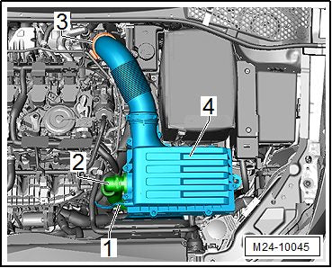
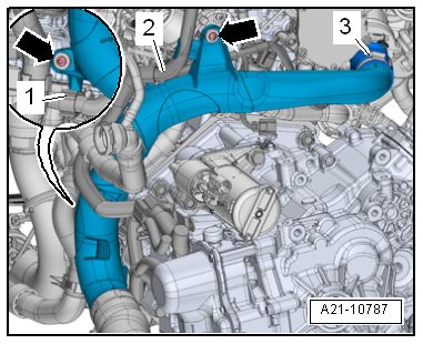
- 1.5 — Free up the wiring harness -1 and 2- from the air guide pipe.
- 1.6 — Loosen the screw-type clamp -3-.
- 1.7 — Remove the bolts -arrows-.
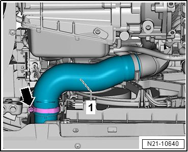
- 1.8 — Loosen the hose clamp -arrow- and remove the left charge air hose -1- with the air guide pipe downward.
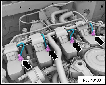
Step 2. Remove Ignition Coils
The ignition coils come out far easier when the engine is warm — the installation grease softens and releases the coils and spark plug connectors more readily.
- 2.1 — If equipped, remove the ground cable -arrows-.
- 2.2 — Release the connector and disconnect all the connectors from the ignition coils at the same time.
- 2.3 — Carefully remove the ignition coils vertically upward using your preferred method (by hand, puller tool, etc.).
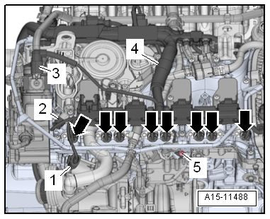
Step 3. Remove Upper Coolant Pipes
- 3.1 — Make sure the engine is cold, then briefly open the coolant reservoir cap to release residual pressure in the system.
- 3.2 — Loosen hose clamps -1-, remove the coolant hose and push it to the right side.
- 3.3 — Release the retainers in the direction of the -arrows- and remove wiring duct -1- from the bracket.
- 3.4 — Clamp off the coolant hoses in the direction of the -arrows- with coolant hose clamps or OE 3094.
- 3.5 — Loosen the clamps and remove the coolant hoses.
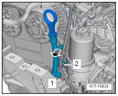
- 3.6 — Remove the bolt -1- and remove the upper coolant pipe.

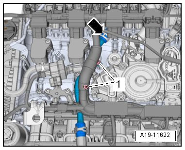
Step 4. Disconnect Engine Connectors & Move Coolant Pipe
-
4.1 — Disconnect the connectors:
- 1 — Turbocharger recirculation valve -N249-
- 2 — Camshaft position sensor 3 -G300-
- 3 — Fuel pressure regulator valve -N276-
- 4.2 — Disconnect the connectors -arrows- from the cam adjustment actuator.
- 4.3 — Remove the bolt -5- and free up the ground cable.
- 4.4 — Free the connector from clip -4- and pivot it forward.
Risk of destroying the coolant pipes through deformation. Never change the bent shape of the coolant pipe.
- 4.5 — Release the retainers in the direction of the -arrow-, remove the wiring duct upward from the bracket and move it toward the front.
- 4.6 — Remove bolts -1, 2 and 3-. Carefully swing the coolant line slightly toward the rear.
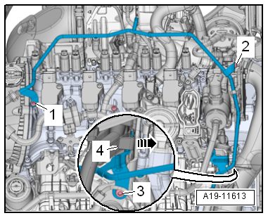
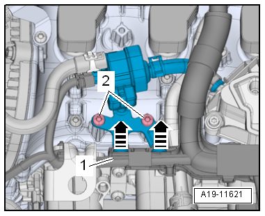
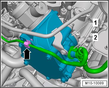
Step 5. Remove Crankcase Ventilation System
- 5.1 — Disconnect connector -1- from the EVAP canister purge regulator valve 1 -N80-.
- 5.2 — Press the release button on the crankcase ventilation hose -2- and remove the hose.
- 5.3 — Remove the bolts -arrows- and the crankcase ventilation.
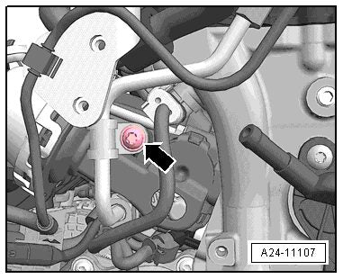
Step 6. Remove High-Pressure Fuel Pump
The fuel system is under pressure — risk of injury from fuel spraying out. Wear protective eyewear and safety gloves. To reduce pressure, place clean cloths around the connection point and carefully open it.
- 6.1 — Remove the pipe clamp -arrow-.
- 6.2 — Counterhold on the hex fitting -A- and loosen the union nut -arrow-. Disconnect the upper side of the high-pressure fuel line.
- 6.3 — Disconnect connector -1- from the fuel pressure regulator valve -N276-.
- 6.4 — For vehicles with multiport fuel injection, loosen spring clamp -3- and the fuel hose.
- 6.5 — For all other vehicles, loosen spring clamp -2- and the fuel hose.
- 6.6 — Remove the bolts -arrows-.
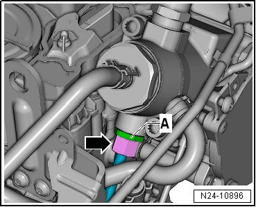
Inspect the O-ring for the high-pressure pump and replace it if damaged.
- 6.7 — Carefully remove the high-pressure pump. The roller tappet -A- may remain in the vacuum pump -B-.
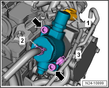
Step 7. Remove Vacuum Pump
- 7.1 — Unclip the vacuum line -2- from the bracket -arrow-.
- 7.2 — Disconnect the vacuum hose -2-.
- 7.3 — Remove the bolts -arrows- and remove the vacuum pump.
Do not disassemble the vacuum pump.
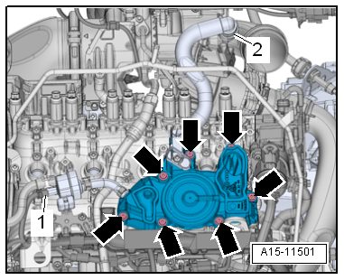
Step 8. Remove Front Timing Cover
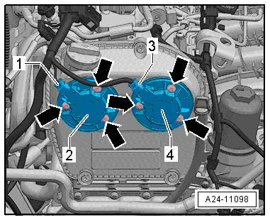
- 8.1 — Remove connector -1- from exhaust camshaft adjustment valve 1 -N318- and connector -3- from camshaft adjustment valve 1 -N205-.
- 8.2 — Remove the bolts -arrows-, camshaft adjustment valve 1 -N205- -4-, and exhaust camshaft adjustment valve 1 -N318- -2-. (Ignore item 2.)
- 8.3 — Remove the bolt -1- and unclip the guide tube from the timing chain upper cover in the direction of the -arrow-.
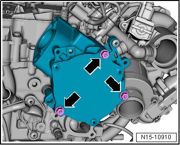
- 8.4 — Remove the bolts -1 through 6- and the upper cover for the timing chain.
With everything removed, the engine is now prepped for installing the camshaft retaining tools. On to Section 2.
Installing the Camshaft Tools
This section explains how the AHMCNC EA888 camshaft retaining tools work and walks through correct installation. As noted earlier, there are small production differences between EA888 generations — certain engines have more cutouts in the cam bridge cover, or slightly different intake camshaft designs — so be aware of possible differences between these photos and your specific vehicle.
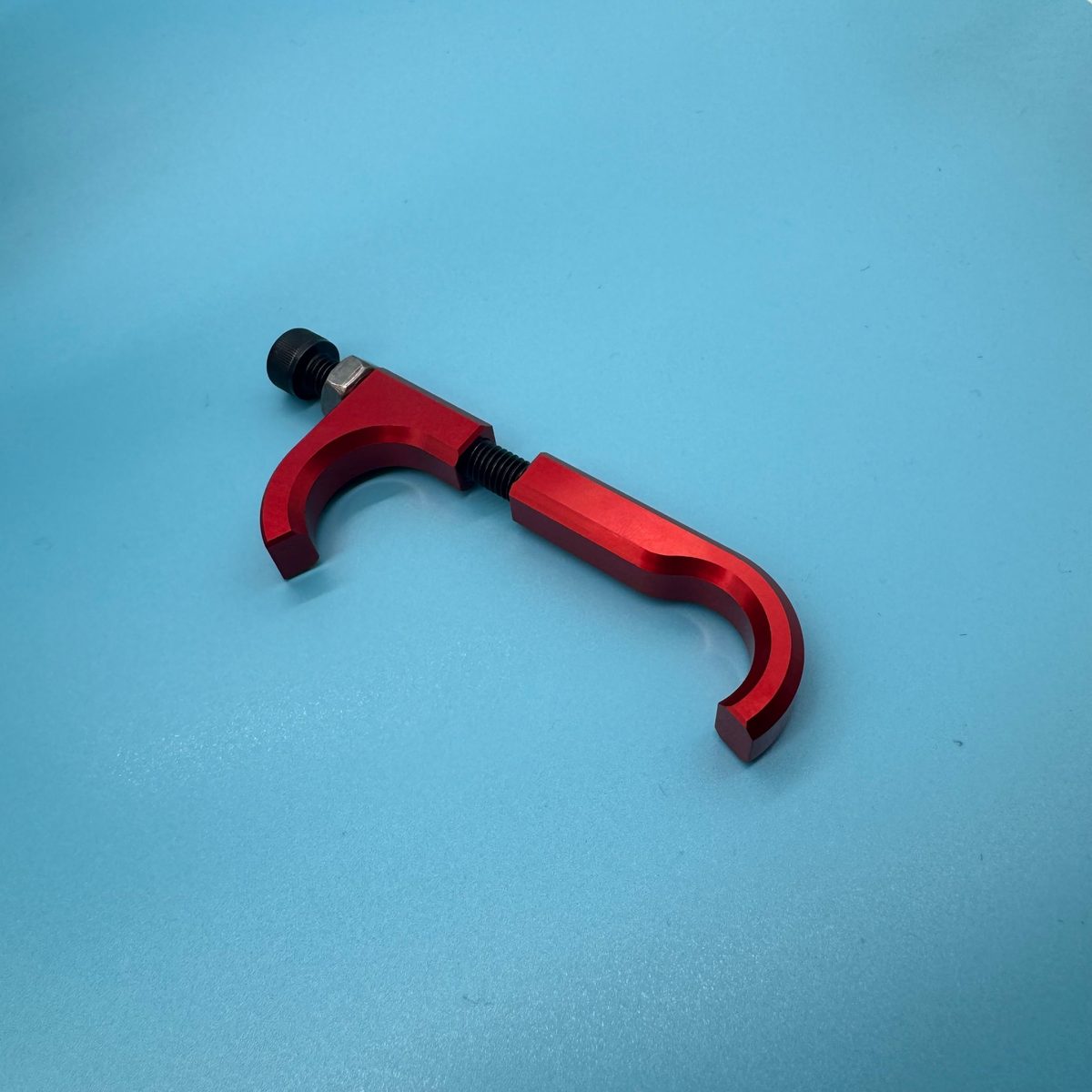
Intake Camshaft Tool
The intake tool uses a dual-hook design. The lower hook is fixed and wraps around the manufacturing casting geometry on the inside of the cylinder head. The upper hook slides freely up and down the bolt; using the locknut, you lock the upper hook onto the intake camshaft — effectively squeezing the intake camshaft into its bearing journal.
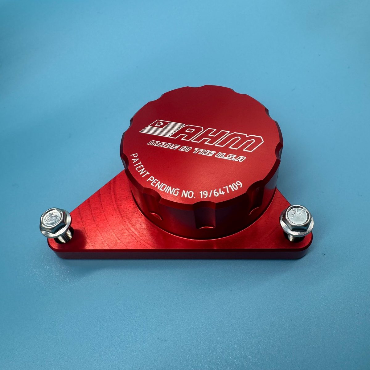
Exhaust Camshaft Tool
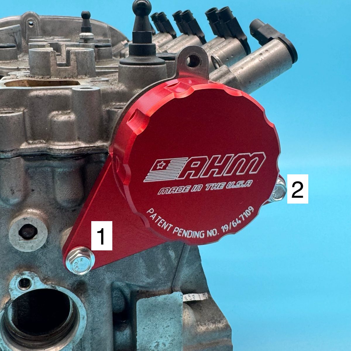
The exhaust tool uses a precision-machined bore that slides over the boss on the end of the exhaust camshaft (the one that drives the vacuum pump). It's installed by bolting to two of the factory vacuum pump mounting locations. Once installed, it locks the exhaust camshaft into its bearing journal.
The installation photos below were taken on a cylinder head removed from the vehicle. Some features may look different from what's on your engine in-car.
Intake Camshaft Tool — Installation
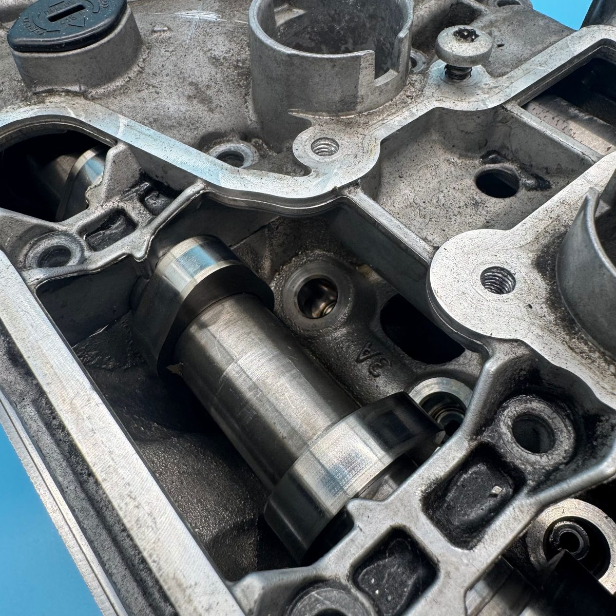
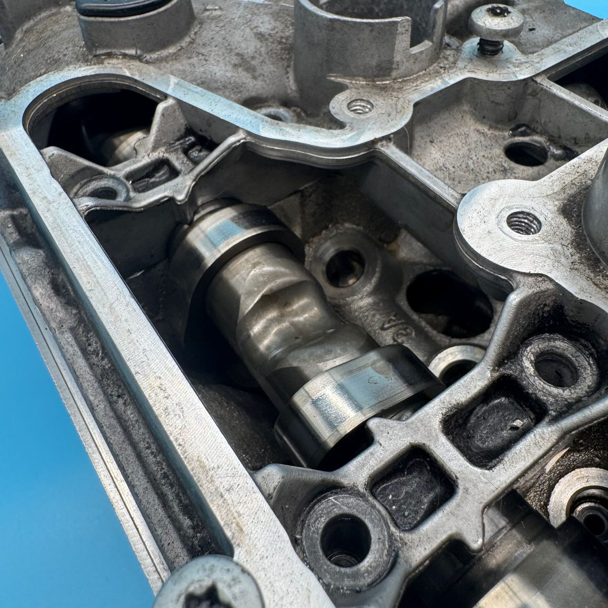
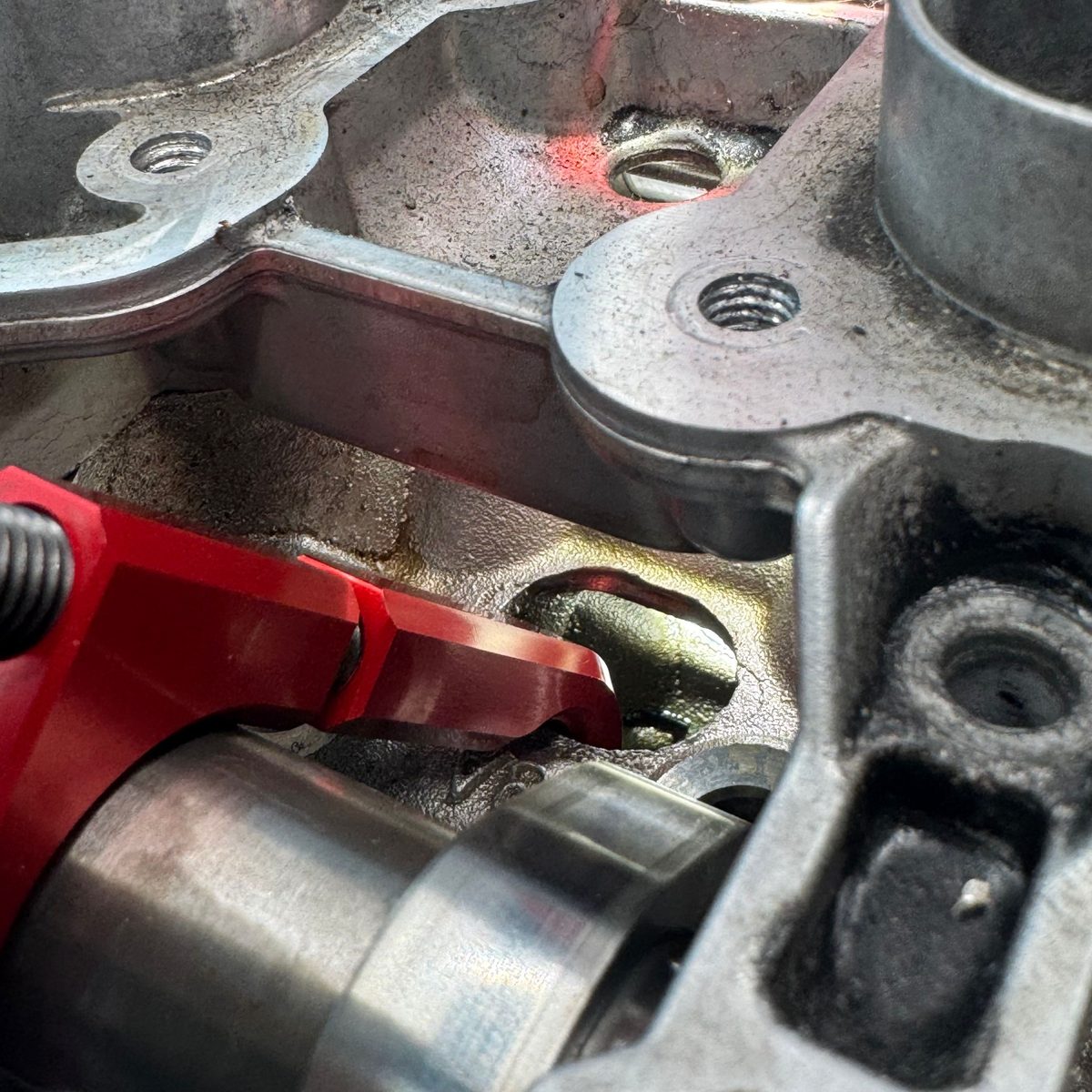
- Step 1 — Locate the opening in the cylinder head cover for the crankcase ventilation system. You'll see the intake camshaft through the opening.
- Step 2 — Verify the orientation of the intake camshaft: the camshaft relief for the head bolts must be facing down, toward the engine — not upward. See Figure 1 for the correct orientation; Figure 2 shows the incorrect orientation. If needed, rotate the engine over until the intake camshaft is correct (Figure 1).
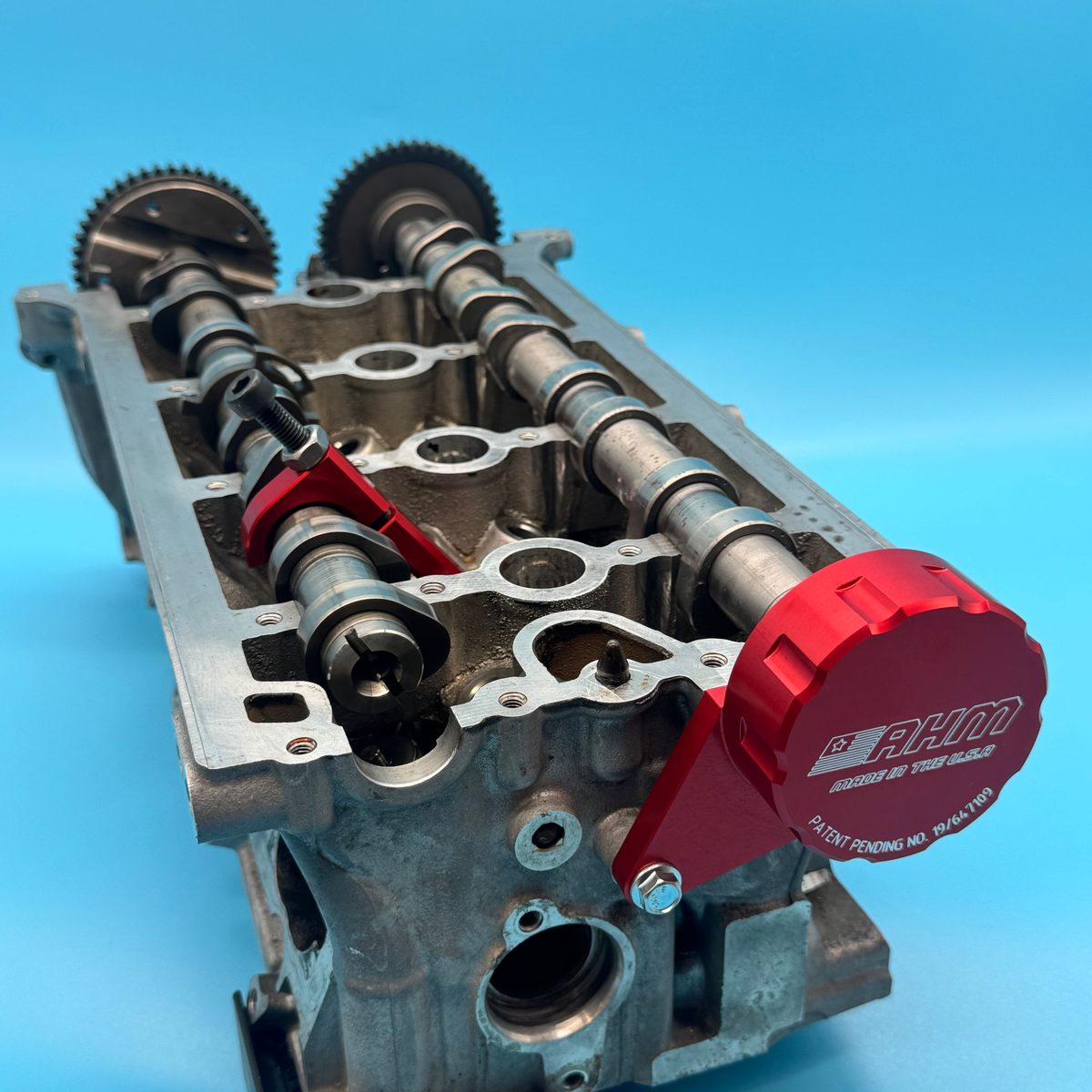
- Step 3 — Insert the intake camshaft tool into the cylinder head cover and rotate the fixed hook around the casting geometry inside the cylinder head.
- Step 4 — Slide the moving hook down onto the intake camshaft and start to thread the locknut down by hand, gently putting pressure onto the moving hook.
- Step 5 — Position both hooks to firmly secure the camshaft into the cylinder head. Tighten the locknut firmly down onto the moving hook to secure the assembly.
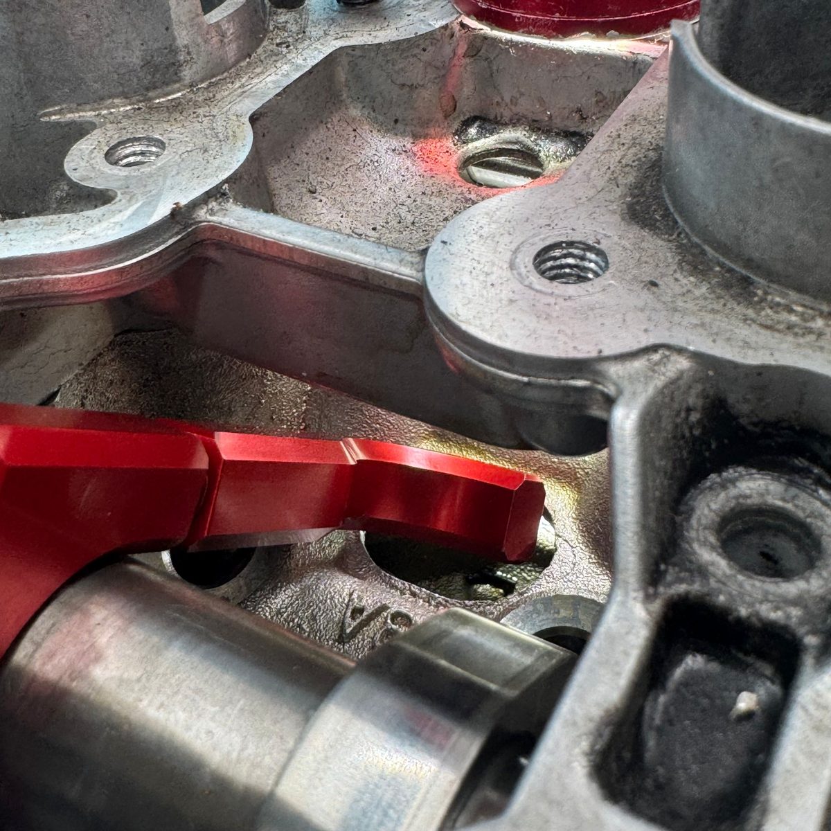
Confirm proper engagement of the lower fixed hook onto the casting geometry. Failure to engage the tool properly may allow the camshafts to shift.
The intake camshaft tool is now fully installed and the camshaft is retained within the cylinder head. Proceed to the exhaust tool.
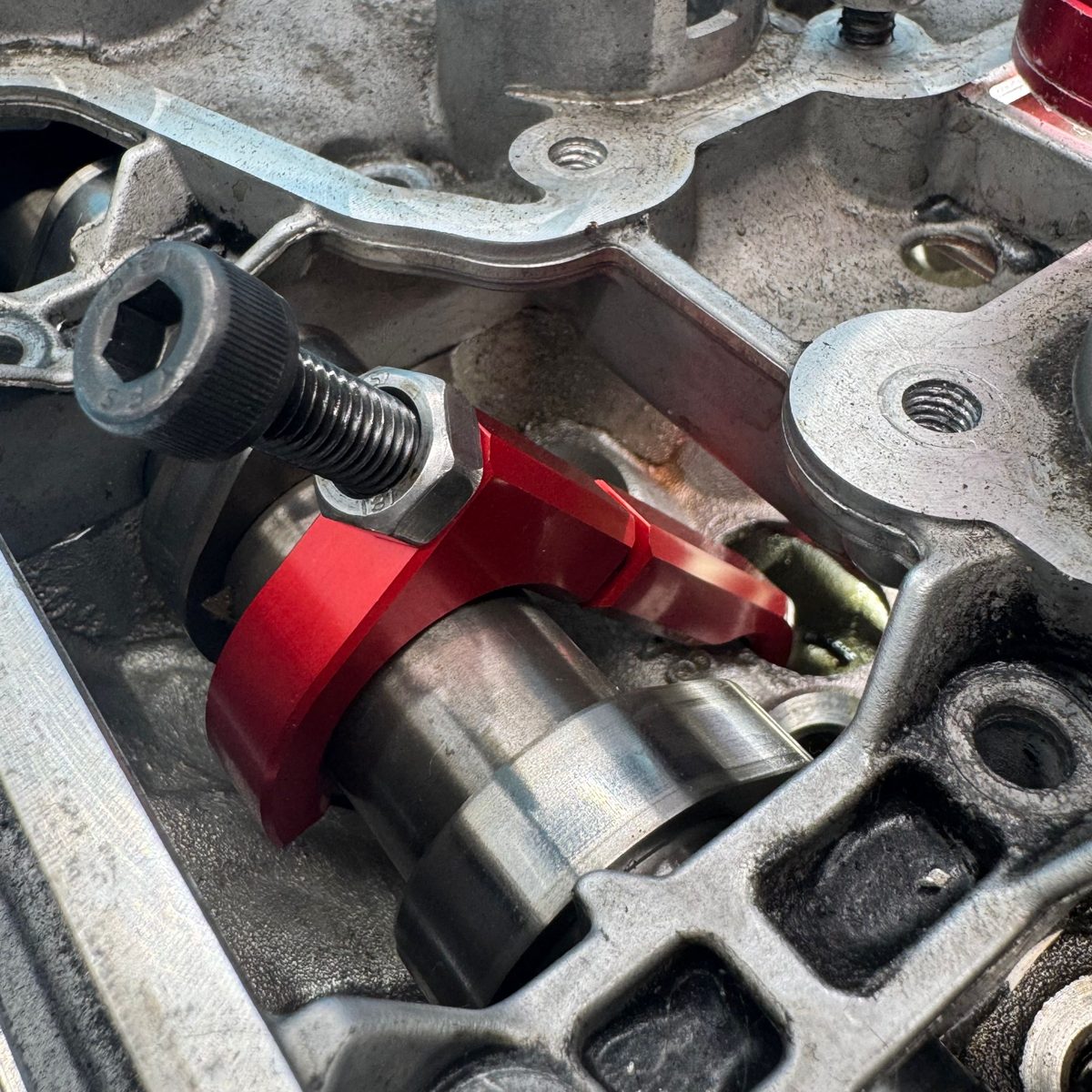
Exhaust Camshaft Tool — Installation
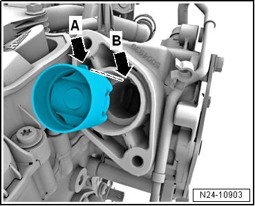
- Step 1 — Locate the boss on the back of the exhaust camshaft that drives the engine vacuum pump.
- Step 2 — Slide the exhaust camshaft tool over the boss and fasten it to the cylinder head with bolts -1, 2-. The exhaust tool is now fully installed.
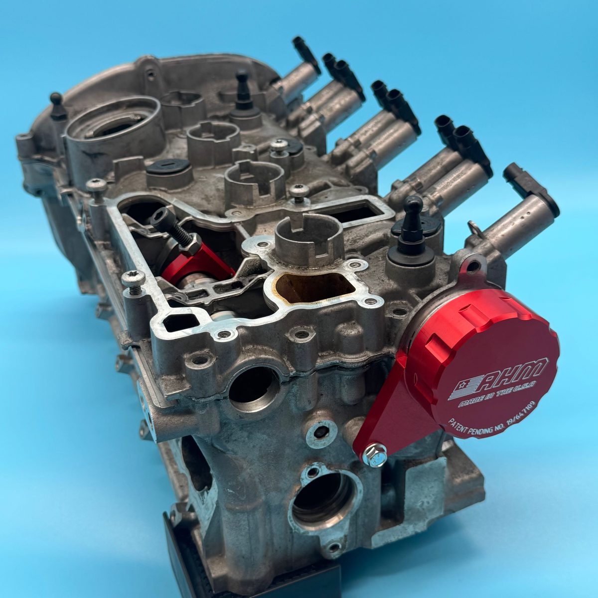
With both tools installed and the camshafts retained, you can safely move on to removing the cylinder head cover.
Cover Removal & Reseal
With the camshafts retained inside the cylinder head, you're ready to remove the cylinder head cover and prepare the mating surfaces for new sealant.
The camshaft bearings are integrated into the cylinder head / cylinder head cover. Before removing the cover, the camshafts must be properly secured with the camshaft retaining tools.
Removing the Cylinder Head Cover
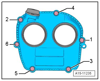
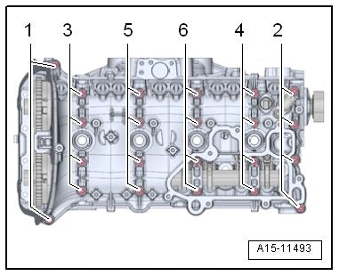
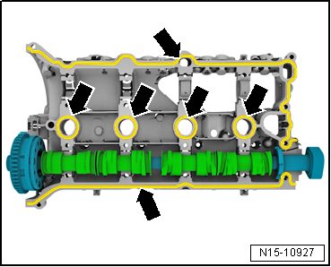
- Step 1 — Remove the cylinder head cover bolts in 1→6 sequence (see Figure 1), then remove the cover. Replace the cylinder head cover bolts after removal.
- Step 2 — With the intake and exhaust tools properly installed, the head will look as shown once the cover is off.
- Step 3 — Remove any sealant residue from the groove on the cylinder head cover and from all sealing surfaces.
Resealing the Cylinder Head Cover
Sealant bead thickness: 2 to 3 mm.
- Step 1 — Apply anaerobic sealant on the clean sealing surface of the cylinder head cover as shown -arrows-.
- Step 2 — Place the cylinder head cover onto the cylinder head, making sure the cover is not tilted.
- Step 3 — Install new cylinder head cover bolts in multiple steps. Use Figure 1 for the tightening sequence and the table below for torque specs.
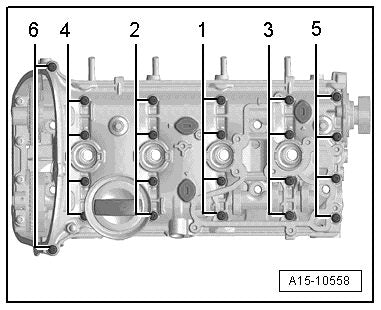
| Step | Bolts | Tightening Specification |
|---|---|---|
| 1 | -1 through 6- | Hand tight |
| 2 | -1 through 6- | 8 Nm |
| 3 | -1 through 6- | Turn an additional 90° |
Reassembly
That's it — you've successfully resealed the cam bridge cover on your EA888 using the AHMCNC camshaft retaining tools. Reinstall the remaining components in the reverse order of removal:
- Install the upper timing cover and related components
- Install the vacuum pump
- Install the high-pressure fuel pump
- Install the crankcase ventilation system
- Reconnect the engine harness connectors
- Install the engine coolant pipes
- Install the ignition coils
- Install the air filter housing and charge air piping
Get the Tools for the Job
The AHMCNC EA888 camshaft retaining tool is precision-machined in the USA and built to lock your camshafts securely for a clean, repeatable reseal.
Shop the EA888 ToolsHave a technical question about our tools? Email us at info@ahmcnc.com. Thank you for choosing AutohausMachine!
